What is QAM?
Quadrature amplitude modulation (QAM) is the name of a family of digital modulation methods and a related family of analog modulation methods widely used in modern telecommunications to transmit information. QAM is both an analog and a digital modulation scheme. It conveys two analog message signals, or two digital bit streams, by changing (modulating) the amplitudes of two carrier waves, using the amplitude-shift keying (ASK) digital modulation scheme or amplitude modulation (AM) analog modulation scheme. A variety of forms of QAM are available and some of the more common forms include 16QAM, 32QAM, 64QAM, 128QAM, 256QAM, 512QAM, 1024QAM, 2048QAM and 4096QAM.
Why are higher QAM levels used?
The various flavors of QAM may be used when data-rates beyond those offered by 8-PSK are required by a radio communications system. This is because QAM achieves a greater distance between adjacent points in the I-Q plane by distributing the points more evenly. And in this way, the points on the constellation are more distinct and data errors are reduced. While it is possible to transmit more bits per symbol if the energy of the constellation is to remain the same, the points on the constellation must be closer together and the transmission becomes more susceptible to noise. This results in a higher bit error rate than for the lower order QAM variants. In this way there is a balance between obtaining the higher data rates and maintaining an acceptable bit error rate for any radio communications system.
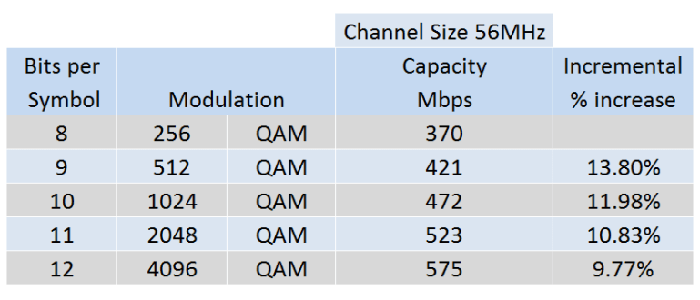
Modern wireless networks often demand and require higher capacities. For a fixed channel size, increasing QAM modulation level increases the link capacity. Note that incremental capacity gain at low-QAM levels is significant; but at high QAM, the capacity gain is much smaller. For example, increasing
- From 1024QAM to 2048QAM gives a 10.83% capacity gain.
- From 2048QAM to 4096QAM gives a 9.77% capacity gain.
Understanding QAM Modulation
Let’s start with the QAM modulation process at the transmitter to receiver in the wireless baseband (i.e. Physical Layer) chain. We will use the example of 64-QAM to illustrate the process. Each symbol in the QAM constellation represents a unique amplitude and phase. Hence they can be distinguished from the other points at the receiver.
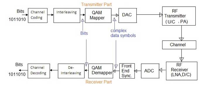
- As shown in the figure above, 64-QAM or any other modulation is applied on the input binary bits.
- The QAM modulation converts input bits into complex symbols which represent bits by variation in amplitude/phase of the time domain waveform. Using 64QAM converts 6 bits into one symbol at transmitter.
- The bits to symbols conversion take place at the transmitter while reverse (i.e. symbols to bits) take place at the receiver. At receiver, one symbol gives 6 bits as output of demapper.
- Figure depicts position of QAM mapper and QAM demapper in the baseband transmitter and receiver respectively. The demapping is done after front end synchronization i.e. after channel and other impairments are corrected from the received impaired baseband symbols.
- Data mapping or modulation process is done before the RF upconversion (U/C) in the transmitter and PA. Due to this, higher order modulation necessitates use of highly linear PA (Power Amplifier) at the transmit end.
QAM Mapping Process
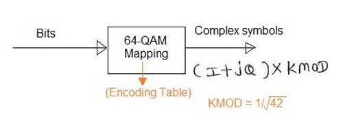
In 64-QAM, the number 64 refers to 2^6.
Here 6 represents number of bits/symbol which is 6 in 64-QAM.
Similarly, it can be applied to other modulation types such as 512-QAM, 1024-QAM, 2048-QAM and 4096-QAM as described below.
Following table mentions 64-QAM encoding rule. Check the encoding rule in the respective wireless standard. KMOD value for 64-QAM is 1/SQRT(42).
| Input bits (b5, b4, b3) | I-Out | Input bits (b2, b1, b0) | Q-Out |
| 011 | 7 | 011 | 7 |
| 010 | 5 | 010 | 5 |
| 000 | 3 | 000 | 3 |
| 001 | 1 | 001 | 1 |
| 101 | -1 | 101 | -1 |
| 100 | -3 | 100 | -3 |
| 110 | -5 | 110 | -5 |
| 111 | -7 | 111 | -7 |
QAM mapper Input parameters: Binary Bits
QAM mapper Output parameters: Complex data (I, Q)
The 64-QAM mapper takes binary input and generates complex data symbols as output. It uses above mentioned encoding table to do the conversion process. Before the coversion process, data is grouped into 6 bits pair. Here, (b5, b4, b3) determines the I value and (b2, b1, b0) determines the Q value.
Example: Binary Input: (b5, b4, b3, b2, b1, b0) = (011011)
Complex Output: (1/SQRT(42))* (7+j*7)
512-QAM modulation
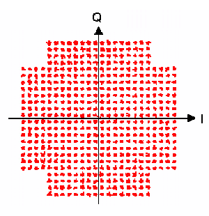
The above figure shows 512-QAM constellation diagram. Note that 16 points do not exist in each of the four quadrants to make total 512 points with 128 points in each quadrant in this modulation type. It is possible to have 9 bits per symbol in 512-QAM also. 512QAM increases capacity by 50% compares to 64-QAM modulation type.
1024-QAM modulation
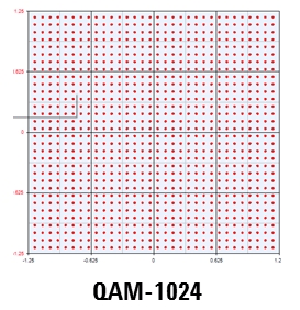
The figure shows a 1024-QAM constellation diagram.
- Number of bits per symbol: 10
- Symbol rate: 1/10 of bit rate
- Increase in capacity compare to 64-QAM: About 66.66%
2048-QAM modulation
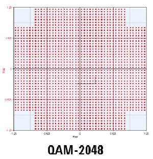
Following are the characteristics of 2048-QAM modulation.
- Number of bits per symbol: 11
- Symbol rate: 1/11 of bit rate
- Increase in capacity from 64-QAM to 1024QAM: 83.33% gain
- Increase in capacity from 1024QAM to 2048QAM: 10.83% gain
- Total constellation points in one quadrant: 512
4096-QAM modulation
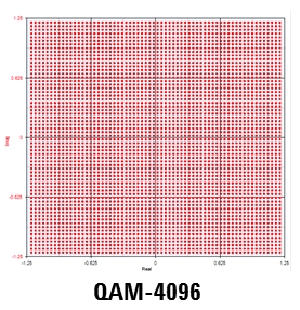
Following are the characteristics of 4096-QAM modulation.
- Number of bits per symbol: 12
- Symbol rate: 1/12 of bit rate
- Increase in capacity from 64-QAM to 409QAM: 100% gain
- Increase in capacity from 2048QAM to 4096QAM 9.77% gain
- Total constellation points in one quadrant: 1024
Advantages of QAM over other modulation types
Following are the advantages of QAM modulation:
- Helps achieve high data rate as more number of bits are carried by one carrier. Due to this it has become popular in modern wireless communication system such as LTE, LTE-Advanced etc. It is also used in latest WLAN technologies such as 802.11n 802.11 ac, 802.11 ad and others.
Disadvantages of QAM over other modulation types
- Following are the disadvantages of QAM modulation:
- Though data rate has been increased by mapping more than 1 bits on a single carrier, it requires high SNR in order to decode the bits at the receiver.
- Needs high linearity PA (Power Amplifier) in the Transmitter.
- In addition to high SNR, higher modulation techniques need very robust front-end algorithms (time, frequency and channel) to decode the symbols without errors.